Introduction to Points Controllers
Point Motors - Snap Action
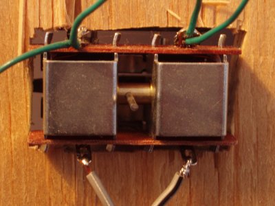
A point motor is a device that is typically but not always marketed by the manufacturers of model railway points. A point motor basically converts an otherwise hand operated set of points into a set of points that may be operated remotely. The picture below is of a Peco PL10 point motor used to convert Peco points to remote operation.
There are three basic ways of attaching a point motor to a set of points. Each has its own list of advantages and disadvantages.
Method 1

The advantage with this method is that because the point motor is directly attached to the points set there is little chance of the mechanism jamming due to misalignment.
The disadvantages with this method are the effort required to cut the rectangular holes in the baseboard and the difficulties associated with changing the model railway layout when there are these rather large holes in the baseboard.
Method 2
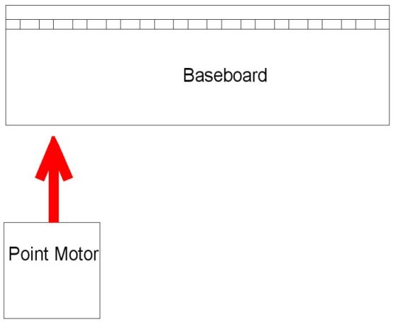
The advantage with this method is that one is only required to cut a small slot in the baseboard instead of the rather large rectangle required by method 1.
The disadvantage with this method occurs because model railway baseboards are typically made of some form of wooden sheeting. Screwing a point motor to such a baseboard is a difficult task to achieve with any precision. Some amount of trail and error with jamming point motor mechanisms is almost an unavoidable consequence of this method.
Method 3
The third method involves mounting the point motor above the baseboard next to the points set using a suitable adapter base. The Peco adapter base is PL-12. The Hornby adapter base is R8015.
The advantages with this method are that no additional slots or holes are required in the baseboard and because a manufacturer's adapter base is being used, precise trouble free operation is almost guaranteed.
The disadvantages with this method are the additional purchase of an adapter base and the requirement for some sort of small building next to each points set to hide the point motor.
No Jamming
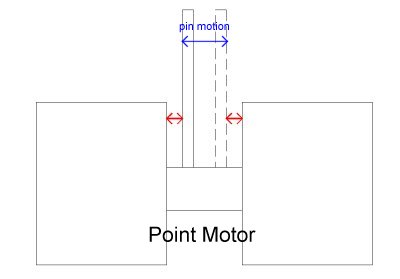
Whatever method is used, care must be taken to ensure that motion of the point motor is as smooth and unimpeded as possible. In particular, care must be taken to ensure that the two extremes of motion of the point motor pin from one points position to the other are equally distanced from the point motor centre. In other words the two red arrows in the following diagram must both be the same length.
Electrical Connections For Snap Action Motors
A snap action point motor requires the connection of three wires, namely one wire for each of the two coils and a third common return wire. The following picture show the terminations on a Dotric Station Blue points controller.

The following diagram illustrates how to electrically connect a point motor to a Dotric Station Blue points controller.

Point Motors - Stall Type
A picture of a stall type point motor is shown below.
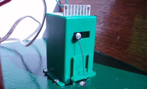
Stall motor advantages include that they are easier to set up for reliable operation and draw a very low current. Disadvantages include that they are more than twice the price of snap action motors. They also take up more space and points with stall motors installed cannot be operated manually.
Electrical Connections
A snap action point motor requires the connection of three wires, namely one wire for each of the two coils and a third common return wire. A stall type point motor requires only two wires - there is no common return.A Dotric Station Blue points controller can control up to 20 points. There are therefore 20 pairs of screw terminals for each of 20 points.
The following diagram illustrates how to electrically connect a stall type point motor to a Dotric Station Blue points controller.

Possible Configurations
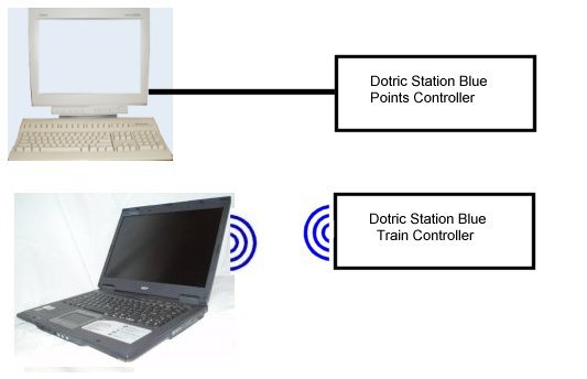
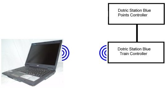
It is entirely possible to purchase a Dotric Station Blue points controller, connect it to a PC and use it to control the points on a model railway completely independent of other systems. Indeed one may purchase a Dotric Station Blue points controller with a serial port and a Dotric Station Blue train controller with Bluetooth and operate them independently. The points controller could be directly connected to a PC to control the points and the train controller could be connected to another PC via Bluetooth to control the trains.
