Introduction to Train Controllers
DC Control
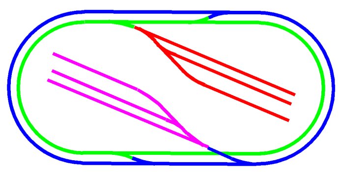
Independent control of a number of basic direct current (DC) locomotives is achieved by dividing the model railway into a number of electrically isolated sections. This is illustrated in the model railway layout shown below where each electrically isolated section of track is represented by a different colour.
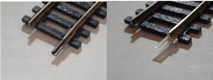
Electrical isolation of the track sections is achieved by replacing the standard metal rail joiners with plastic insulated joiners (such as Peco SL-11) at the section boundaries. This process is illustrated below. On the left is a piece of track as normally supplied, fitted with a metal joiner. On the right is the same section of track with the metal joiner removed and replaced with a plastic insulated joiner.
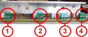
Dotric Station Blue train controllers have four separate outputs that may be used for the control of DC locomotives. So for our example, the four sections of track could be connected to one Dotric Station Blue train controller as shown below.
Digital (DCC) Control
With a Dotric Station Station Blue train controller any of its four outputs may be switched to digital control using a single mouse click. Digital control supplies digitally encoded pulses to the track as described by the National Model Railway Association (NMRA) Digital Command Control (DCC) standard. Referring back to our example, you could be running basic DC locomotives on the green loop and fully functioning digital (DCC) locomotives on the blue loop. Perhaps you would like the blue loop and the pink sidings under DCC control with the green loop and the red sidings under DC control.Better still, because switching from DC to DCC and vice versa is a simple mouse click, you can strategically operate both DC and DCC locomotives across the whole layout switching from one mode to the other as necessary. It is also useful to realize that most DCC decoders by default allow DCC locomotives to operate as DC locomotives when DC is applied. Most DCC decoders may also be configured to not run the DCC locomotive when DC is applied. DC locomotives of course do not run when DCC is applied.
Driver Allocation
The business of utilizing several train controller devices operated by several drivers is handled by Dotric Station Blue using a process called Driver Allocation.The user at a computer set up as a base controller has a train controller page for each of the DC track sections and digital (DCC) locomotives operating on the layout. This user may allocate any one or a number of these track sections and locomotives to any one of the drivers on connected computers or Android devices.